Electrolytic capacitors and ceramic capacitors do different jobs in circuits. Designers pick ceramic capacitors for high-frequency or exact uses. These capacitors work well and are not polarized. Electrolytic capacitors are better for smoothing power supplies. They have higher capacitance and can handle more current.
The table below shows the main differences between these two capacitor types:
| Feature | Ceramic Capacitors | Electrolytic Capacitors |
|---|---|---|
| Capacitance Range | Low to moderate | High |
| Polarity | Non-polarized | Polarized |
| Aluminium Use | Not used | Aluminium as main element |
| Stability | Great temperature stability | Less stable, especially at high temps |
| Typical Applications | Signal filtering, decoupling | Power supply smoothing, bulk storage |
Picking the right aluminium-based capacitor or ceramic capacitor helps circuits work well in many designs.
Key Takeaways
-
Electrolytic capacitors can hold more charge. They work well for smoothing power and storing energy. They need the right polarity to work. They are bigger than ceramic capacitors.
-
Ceramic capacitors are small and stable. They do not have polarity. They are good for high-frequency circuits. They help with signal filtering. They fit well in small designs.
-
Electrolytic capacitors leak more and do not like heat. Ceramic capacitors leak less. They last longer when temperatures change.
-
You must pick the right capacitor for your needs. Think about capacitance, voltage, size, frequency, and reliability. Using both types together often helps circuits work best.
-
Do not forget about voltage ratings, temperature, and ESR. These things help capacitors work well and last longer in electronics.
Construction
Electrolytic Capacitors: Structure
Electrolytic capacitors are built in a special way. Makers use metals like aluminium, tantalum, or niobium. They form a thin oxide layer on the metal using electricity. This layer is called the dielectric. Most aluminium electrolytic capacitors use etched aluminium foils. Etching makes the surface bigger, so capacitance goes up. The foils are rolled with a separator. They soak everything in an electrolyte. Then, they seal it in a cylinder to keep moisture inside.
The kind of anode and dielectric picked changes how much charge the capacitor holds, how much voltage it can take, and how long it lasts. The table below shows how different aluminium electrolytic capacitors compare:
| Anode Material | Dielectric Oxide | Relative Permittivity | Breakdown Voltage (V/μm) | Electric Layer Thickness (nm/V) |
|---|---|---|---|---|
| Aluminum | Aluminum oxide (Al2O3) | 9.6–14.2 | 710–1000 | 1.0–1.4 |
| Tantalum | Tantalum pentoxide (Ta2O5) | 27 | 625 | 1.6 |
| Niobium | Niobium pentoxide (Nb2O5) | 41 | 400 | 2.5 |
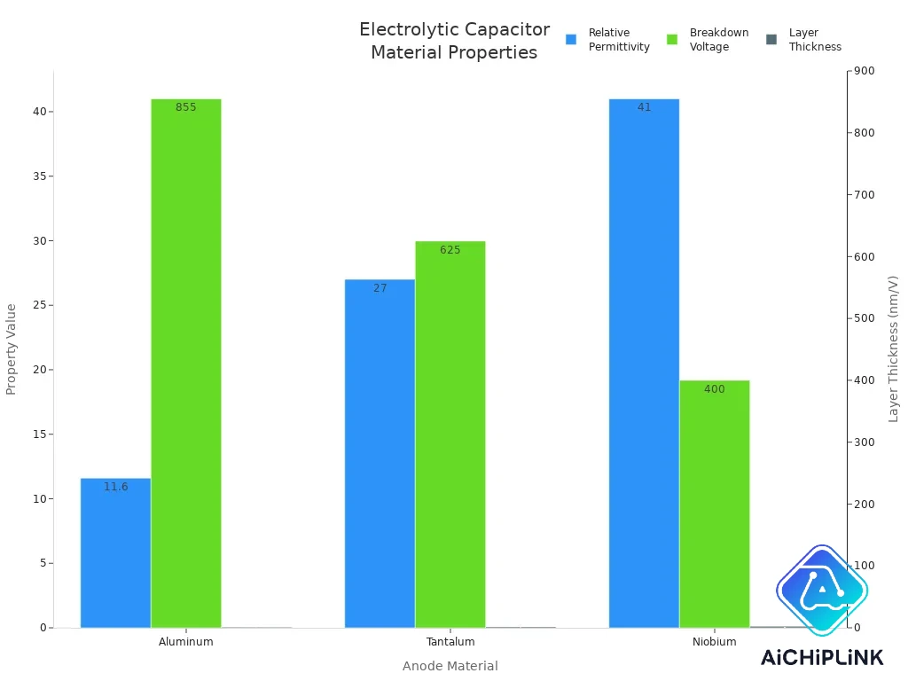
Aluminum electrolytic capacitors can hold a lot of charge and work with high voltages. But they do not last forever. The liquid inside can dry up, which makes them less strong. These capacitors are bigger, so they cool down better. But their size means they do not fit well in small spaces.
Ceramic Capacitors: Structure
Ceramic capacitors are made in another way. Makers mix ceramic powder with liquid to make a slip. They spread this slip into thin sheets. Metal electrodes are printed on each sheet. The sheets are stacked and pressed together. They cut the stack, burn out glue, and heat it to make a solid block. This makes layers of ceramic and metal plates. The result is a small and steady capacitor.
Ceramic capacitors can look like discs or tubes. Metal contacts are added by chemical methods or by spraying. MLCCs are tiny, cheap, and have low ESR. This makes them great for fast signals and crowded circuit boards. The solid ceramic inside helps them last a long time. Many ceramic capacitors work for decades.
Ceramic capacitors are tough and steady. Aluminium electrolytic capacitors hold more charge for power jobs. How each type is built decides where it works best in electronics.
Performance
Capacitance Range
Capacitance tells us how much charge a capacitor can hold. Electrolytic capacitors have many capacitance choices. Most start at 1 microfarad and go up to thousands. Some special aluminium electrolytic capacitors can reach farad levels. Ceramic capacitors have lower values. They range from 1 picofarad to 100 nanofarads. Some mlcc types can reach low microfarad levels. Designers use ceramic capacitors for signal filtering and timing. These jobs need small and exact capacitance. Electrolytic capacitors are good for storing energy and smoothing power.
| Capacitor Type | Typical Capacitance Range |
|---|---|
| Electrolytic | 1 µF to several thousand µF |
| Ceramic | 1 pF to 100 nF (low µF for MLCC) |
Ceramic capacitors work well in high-frequency circuits. Their stable and low capacitance helps. Electrolytic capacitors are best for power jobs. They have large capacitance.
Voltage Ratings
Voltage rating shows the highest voltage a capacitor can take. Electrolytic capacitors usually have lower voltage ratings. Most aluminium types are between 6 V and 50 V. Some can go up to 450 V. High capacitance at high voltage is rare. Ceramic capacitors can handle much higher voltages. Some types are rated up to 2000 V. This makes ceramic capacitors great for high voltage circuits. They are used in power supplies and RF applications.
| Capacitor Type | Voltage Rating | Capacitance Range | Polarity | Practical Application Context |
|---|---|---|---|---|
| Ceramic Capacitors | High (up to 2000 V) | Low (up to 2 µF) | Non-polarized | High voltage, low capacitance circuits |
| Electrolytic Capacitors | Low (35 V to 450 V) | High (up to 20,000 µF) | Polarized | Low voltage, high capacitance, DC power supplies |
-
Electrolytic capacitors are best for high capacitance at low voltage.
-
Ceramic capacitors are good for high voltage with lower capacitance.
ESR and Leakage
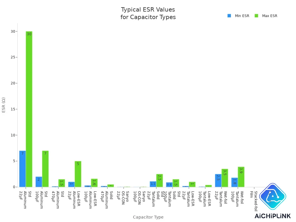
Equivalent Series Resistance (ESR) affects how capacitors work in circuits. Ceramic capacitors have very low esr. It is often less than 0.015 ohms. This makes them great for fast and high-frequency jobs. Electrolytic capacitors have higher esr. Standard aluminium types show this most. ESR goes down as capacitance goes up. But even low-esr aluminium electrolytic capacitors cannot beat ceramic types.
| Capacitor Type | Typical ESR Range (Ω) for Various Capacitances |
|---|---|
| Standard aluminum (22 μF) | 7 to 30 Ω |
| Standard aluminum (100 μF) | 2 to 7 Ω |
| Standard aluminum (470 μF) | 0.13 to 1.5 Ω |
| Low-ESR aluminum (22 μF) | 1 to 5 Ω |
| Low-ESR aluminum (100 μF) | 0.3 to 1.6 Ω |
| Solid aluminum (470 μF) | 0.2 to 0.5 Ω |
| Sanyo OS-CON (22 μF) | 0.04 to 0.07 Ω |
| Sanyo OS-CON (100 μF) | 0.03 to 0.06 Ω |
| Stacked-foil film | < 0.015 Ω |
| Ceramic | < 0.015 Ω |
Leakage current is also important. Electrolytic capacitors, especially aluminium types, leak more than ceramic capacitors. Leakage gets worse with heat and higher voltage. Aluminium electrolytic capacitors can fix small problems inside. This helps lower leakage over time. Ceramic capacitors leak less. Their dielectric properties make them react differently to temperature. Both types show dielectric absorption. High dielectric constant types absorb more.
-
Electrolytic capacitors: Leak more, especially when hot.
-
Ceramic capacitors: Leak less, stay steady most of the time.
Polarity
Polarity is important for how capacitors work and last. Electrolytic capacitors are polarized. The aluminium oxide layer forms only on the anode. You must connect the positive side to the right voltage. If you reverse the polarity, the oxide layer can break. This causes leaks, failure, or damage. Ceramic capacitors are non-polarized. Their ceramic dielectric is the same on both sides. You can connect them any way. This makes them safer and easier for AC circuits.
| Feature | Electrolytic Capacitors (Polarized) | Ceramic Capacitors (Non-Polarized) |
|---|---|---|
| Dielectric Material | Asymmetric oxide layer on anode (electrolytic) | Symmetrical ceramic dielectric |
| Polarity Requirement | Must be connected with correct polarity (+ to anode) | No polarity requirement; can be connected either way |
| Capacitance | Higher for given size | Lower for given size |
| Operational Risk | Reverse polarity can cause failure | No risk from reversed polarity |
| Application Examples | Power supply filtering, smoothing | Signal coupling, AC filtering |
Polarity is very important for electrolytic capacitors. Ceramic capacitors are easier to install and safer.
Temperature Stability
Temperature changes how capacitors work and last. Electrolytic capacitors do not like heat. High temperatures dry out the electrolyte. This makes leakage worse and shortens life. Capacitance can change a lot when hot. Ceramic capacitors, especially Class I, handle temperature well. Their capacitance stays almost the same. Class II and III ceramic capacitors have more capacitance but are less steady.
| Capacitor Type | Temperature Stability Characteristics |
|---|---|
| Electrolytic | Sensitive to temperature; capacitance varies; lifespan reduced at high temps; risk of drying out or bursting |
| Ceramic (Class I) | Excellent stability; minimal capacitance change over wide temperature range |
| Ceramic (Class II & III) | More variable capacitance with temperature; higher capacitance density but less stable than Class I |
-
Ceramic capacitors: Best for circuits that need steady performance in changing temperatures.
-
Electrolytic capacitors: Need careful temperature control for long life.
Reliability
Reliability means how well a capacitor avoids breaking over time. Aluminium electrolytic capacitors often fail because esr goes up, electrolyte dries out, or they get damaged. Their life gets cut in half for every 10°C rise in temperature. Ripple current and bad storage also lower reliability. Ceramic capacitors are usually more reliable if treated well. Most problems come from cracking due to stress or heat changes. SMD ceramic capacitors are brittle. Better manufacturing has made them stronger.
| Aspect | Aluminum Electrolytic Capacitors | Ceramic Capacitors |
|---|---|---|
| Common Failure Modes | Increased ESR, electrolyte drying, oxide film dissolution, leakage, mechanical damage | Cracking, oxygen migration, short circuit |
| Sensitivity Factors | Temperature, ripple current, storage, chemical exposure | Mechanical stress, thermal mismatch, humidity |
| Life Estimation Formula | LT = LR * (ER/EO) * 2^(ΔT/10) (liquid electrolyte) | L = LR * (ER/EO)^3 * (TR/TO)^8 |
| Notes on Life and Reliability | Life halves every 10°C rise; ESR increase signals end-of-life; quality varies by manufacturer | Reliable if not abused; SMD types brittle; oxygen migration limits life at high temp and voltage |
| Mechanical Considerations | Axial leads prone to vibration damage; SMD types prone to leakage; poor heat dissipation | SMD ceramics brittle; mounting affects cracking risk; improved manufacturing reduces failures |
| Storage and Handling | Storage increases leakage; reforming recommended; sensitive to solvents | Less affected by storage; inspection possible |
| Manufacturer and Application Notes | NASA avoids aluminum electrolytics in flight hardware; tantalum or solid electrolytics preferred for high reliability | Smaller sizes reduce stress; lead-frame ceramics more robust but costly; manufacturing improvements ongoing |
To make capacitors last longer, keep electrolytic capacitors cool and limit ripple current. Handle ceramic capacitors carefully to avoid cracks, especially SMD types.
Applications
Electrolytic Capacitor Uses
Electrolytic capacitors are important in many electronics. Engineers pick them when circuits need to store lots of energy. These capacitors are used in many ways:
-
Power supply circuits: They help keep voltage steady and smooth out changes.
-
Decoupling: They block unwanted signals so sensitive parts work better.
-
Filtering: Audio devices use them to clean up sound and remove noise.
-
Timing: Oscillator circuits use them to set timing and frequency.
-
Energy storage: Flash cameras use them to store and quickly release energy.
-
Motor starter circuits: They give motors a boost to start running.
-
Lighting ballasts: They help lamps shine with steady light.
-
Switching power supplies: They help control voltage in computers and LED lights.
-
Telecommunications: They help signals stay clear for good communication.
Tip: Always make sure you connect the positive and negative sides correctly when putting in electrolytic capacitors. This helps stop the circuit from breaking.
Ceramic Capacitor Uses
Ceramic capacitors, especially surface mount types, are found in almost all modern electronics. They are small, steady, and have low resistance. This makes them great for many uses. Engineers use them for:
-
Decoupling: They lower noise in power supplies and keep voltage steady.
-
Filtering: They block signals you do not want in audio and other circuits.
-
Coupling: They connect circuit parts without letting DC voltage pass through.
-
Energy storage: Surface mount types store small amounts of energy for quick use.
-
Consumer electronics: Phones, laptops, and TVs use them for filtering and storing energy.
-
Automotive electronics: ABS, traction control, and engine controls use them for steady work.
-
Industrial and medical devices: Power supplies and motor controls use them for their steady performance.
Surface mount capacitors and polymer capacitors often work together to make decoupling better.
High-Frequency and Power Applications
Ceramic capacitors and polymer capacitors are great for high-frequency circuits. They have low resistance and inductance. This helps signals stay strong and saves energy. The table below shows how they compare to electrolytic capacitors:
| Performance Aspect | Ceramic Capacitors | Electrolytic Capacitors |
|---|---|---|
| ESR | Low, good for high-frequency circuits | Higher, not as good for high frequencies |
| ESL | Low, keeps signals clear | Higher, not as good for high-frequency use |
| Self-Resonant Frequency | High, works well for RF and signal jobs | Low, not good for high-frequency |
| Capacitance Stability | Stays steady with frequency and temperature | Drops as frequency goes up |
| Typical Applications | High-frequency, RF, signal processing | Power supply filtering, low-frequency power |
| Capacitance Value | Lower, but stays steady | High, best for power jobs |
| Usage Strategy | Used alone or with polymer capacitors | Used for storing lots of energy in power circuits |
Polymer capacitors, tantalum capacitors, and surface mount capacitors are often used with ceramic capacitors to make circuits work better. Tantalum and polymer types are more reliable and steady in tough places. Engineers pick the right mix based on how much frequency, power, and reliability the job needs.
Choosing a Capacitor
Selection Factors
Picking the right capacitor for a circuit takes careful thought. Engineers look at many things before choosing. They check capacitance, voltage rating, size, and cost. They also think about temperature range and how the capacitor reacts to different frequencies. ESR, dissipation factor, tolerance, polarization, and DC biasing effects matter too. Ceramic capacitors, like MLCCs, are great for high-frequency jobs. They have low ESR, are small, and do not cost much. Their capacitance can change with temperature and DC bias. Designers need to remember this when planning circuits. Electrolytic capacitors can hold more charge and work with higher voltages. But they have higher ESR and are bigger. Polymer capacitors and tantalum capacitors are good for special needs. They can be more reliable or have lower ESR. The materials and how they are made change the price. Ceramic capacitors usually cost less if you need low capacitance. Where you buy them matters too. Online stores have more choices and better prices.
| Factor | Ceramic Capacitors (MLCCs) | Electrolytic Capacitors (Aluminum) |
|---|---|---|
| Capacitance | Moderate, varies with DC bias and temperature | High capacitance values |
| Voltage Rating | Generally lower, stable for high-frequency use | Higher voltage ratings |
| Size | Compact, small footprint | Larger size |
| Cost | Cost-effective, especially in high volumes | Competitive, may impact system cost due to size |
| Temperature Range | Up to 200°C, capacitance varies with temperature | 85°C to 150°C, temperature-dependent characteristics |
| Frequency Response | Excellent for high-frequency applications | Limited high-frequency performance |
| ESR | Low ESR, ideal for high-frequency circuits | Higher ESR, less suitable for high-frequency use |
| Dissipation Factor | Lower, better efficiency | Higher, more power loss |
| Tolerance | Typically ±5% | Typically ±20% |
| Polarization | Non-polarized | Polarized |
| DC Biasing Effects | Capacitance can decrease under DC bias | Less affected by DC bias |
Common Mistakes
Sometimes engineers make mistakes when picking capacitors. The most common errors are easy to avoid.
-
Not checking voltage ratings can break the capacitor.
-
Forgetting about temperature changes can make capacitance unstable.
-
Picking the wrong capacitance value can mess up filtering.
-
Ignoring ESR can cause power loss and overheating.
-
Not thinking about lifespan and reliability can make the capacitor fail early.
Electrolytic capacitors are best for storing lots of energy and low-frequency filtering. Their higher ESR makes them less good for high-frequency jobs. Ceramic capacitors work better at high frequencies. They often help electrolytic types in mixed designs. Some regulators need certain ESR values. Sometimes you need both types for the best results. Engineers should match the capacitor to the circuit’s frequency and current needs.
Quick Guide
Here is a simple table to help you choose between electrolytic and ceramic capacitors:
| Criteria | Electrolytic Capacitors | Ceramic Capacitors |
|---|---|---|
| Frequency Range | Best for low-frequency applications | Ideal for high-frequency applications |
| Capacitance | High capacitance in compact size | Moderate capacitance, high capacitance per unit volume |
| Polarity | Polarized | Non-polarized |
| Stability | Sensitive to temperature and frequency; higher tolerance | Excellent stability (Class 1), lower tolerance (Class 2) |
| Common Uses | Smoothing voltage fluctuations | Filtering, tuning, decoupling |
| Cost | Generally higher cost | Low cost |
| Additional Notes | Leakage current and parasitic inductance present | Available in multiple shapes and sizes |
Tip: For high-frequency circuits, ceramic capacitors and polymer capacitors work best. For storing lots of energy or filtering power supplies, use electrolytic or tantalum capacitors. Always check the voltage rating, ESR, and where the capacitor will be used before you decide.
Picking the right capacitor helps circuits work better and last longer. Electrolytic capacitors can hold a lot of energy. They are good for power supply filters. Ceramic capacitors are best for high-frequency jobs and small designs. Engineers who know these differences make fewer mistakes. Their electronics projects work better.
-
Electrolytic capacitors need the right polarity. They store lots of energy.
-
Ceramic capacitors stay steady, fit in small spaces, and filter signals well.
Knowing about capacitor types helps designers build strong and useful electronics.
FAQ
What is the main difference between electrolytic capacitors and ceramic capacitors?
Electrolytic capacitors use an aluminum oxide layer and electrolyte. This lets them hold a lot of charge. Ceramic capacitors use a ceramic dielectric. They are steady and have low ESR. Each type works best for different jobs. Their performance and reliability are not the same.
Can ceramic capacitors replace electrolytic capacitors in power supply applications?
Ceramic capacitors are good for filtering and decoupling at high frequencies. They cannot store as much energy as aluminum electrolytic capacitors. Engineers pick the right capacitor for each job. The choice depends on what the circuit needs.
Why do electrolytic capacitors have polarity while ceramic capacitors do not?
Electrolytic capacitors are polarized because of their special aluminum oxide layer. Ceramic capacitors have a ceramic dielectric that is the same on both sides. You can connect ceramic capacitors any way you want. This makes installation easier and safer.
What causes leakage in capacitors, and how does it affect performance?
Leakage happens when current goes through the dielectric. Electrolytic capacitors leak more, especially when hot. Ceramic capacitors leak less, so they last longer. Less leakage means better performance and reliability.
Are multi-layer ceramic capacitors (MLCC) suitable for surface mount applications?
MLCCs have low ESR and work well in many circuits. Engineers use them for decoupling, signal filtering, and high-frequency jobs. Their small size and strong performance fit modern electronics.

Written by Jack Elliott from AIChipLink.
AIChipLink, one of the fastest-growing global independent electronic components distributors in the world, offers millions of products from thousands of manufacturers, and many of our in-stock parts is available to ship same day.
We mainly source and distribute integrated circuit (IC) products of brands such as Broadcom, Microchip, Texas Instruments, Infineon, NXP, Analog Devices, Qualcomm, Intel, etc., which are widely used in communication & network, telecom, industrial control, new energy and automotive electronics.
Empowered by AI, Linked to the Future. Get started on AIChipLink.com and submit your RFQ online today!


